

I am keeping myself entertained by mostly reinventing the wheel, whilst not to losing sight of the fact I’m genuinely trying to make a competitive model for the most technologically advanced control line racing class.
The most inefficient way to design stuff…
…..is to go ‘organic’, but I knew that. Some stuff can only be sorted with a little rigging up and visualisation. And masking tape. Lots and lots of masking tape.

The world’s top F2C manufacturers spend hundreds hours working with computers making complex 3D models (drawings), programming exotic CNC machinery, whilst utilising tooling and materials the rest of us can only dream of. They have incredible technical skill and are usually professionals in their field with access through their work to resources out of reach of mere mortals.
A few years ago this would have all been sketched out on British Standard fag packet (BS No.6), probably with a quill pen fresh from a goose’s arse. I may be getting my eras slightly mixed up but following a noughties risk assessment no one half sensible smokes any more, so I have a sharpened Staedtler HB and a fresh sheet of A4 at the ready. Keep it current!
My head hurts
My method involves many and various hand tools. I usually indulge bit of model comparison, sketching and measuring. Lots of hand work, usually with some repeating because I’d done it wrong, or I could see a simple improvement. I can see why 3D modelling and CNC machines are things. Very clever things that make skill and unnecessary commodity. But handmade in Hampshire has the bonus of being the ideal way to produce one of experimental models.
Later though, in a rare moment of clarity or possibly desperation, I sought the help of an expert.
First step with the design of the internals, the engine cooling duct, U/C mount and engine bay floor were rattling round in my mind. F2C engines vary in their mounting hole pattern and cylinder diameter. As I wanted the duct to fit within a maximum of 0.5mm, the Sosnovsky at 30.0mm and Zalp at 30.5mm were going to need different mouldings. Fortunately Matthieu Perret came to the rescue for Fing2C 001, as he had ducts to suit the Sosnovski . Merci beaucoup!
The Zalp is a smidge large for Matt’s mouldings so I embarked on a separate cylinder and duct mould using conventional methods.
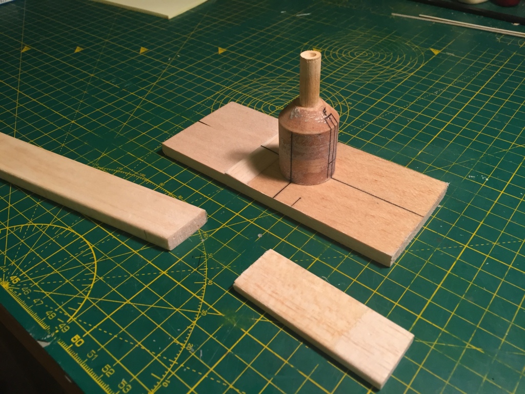
Bits of balsa were shaped and cover in light glass-cloth. A cylinder diameter of 31.0mm gave the desired clearance.

At this stage I had by chance started talking to a CNC professional, who offered help and advice on 3D-modelling, which I was playing around with and getting a little confused by. He also offered to work out the tool paths and cut the duct mould. I’m sure he was driven mainly by sympathy at my pathetic efforts, but his input was very gratefully received! That was Fing2C 002 started, back to actually building Fing2C 001
Model #001
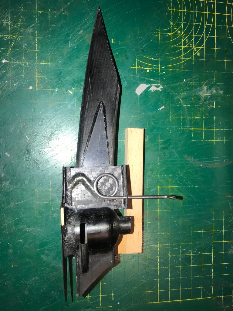
The design of the U/C mounting gave me much food for thought. Ideally the assembly, which is a direct copy of the Original models’ system, would be removable. However as this was a first attempt I decided to live with a bonded in item. The L shaped carbon plate has the leg sewn on using lightweight Laystrate anchored with 24hr Araldite epoxy. In the assembled model it has a really nice smooth action and I’m hopeful this Heath-Robinson looking approach will be effective in use. It feels great, costs pennies and literally minutes of hand work to make. At this point I had no idea how to fix it into the lower section of the bottom shell.

Matthieu Perret came to the rescue with these duct halves for Sosnovski
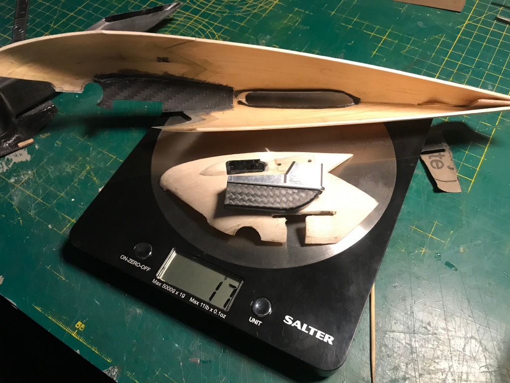
To spread the loads from landing into the lower shell another carbon plate was mounted internally. Carbon tows are formed around the inside edge of the duct outlet to give a solid gluing area. The bottom cowl is lined with 48g glass-cloth and at this stage is fitted with the tail under-fin. Also present is the Profi exhaust shroud including carbon insert and m2 mounting plate, all fitted to the front 1/4 inboard lower shell.
Duct and undercarriage
Much procrastination occurred as the layout of the mouldings was giving me a headache. It may be overkill, but the U/C is anchored on the underside of the wing, on the duct side and the shell base.
In the cold light of day the first incarnation will probably work well, and I believe it can be made removeable on subsequent racers.


Once assembled the completed duct and U/C signified the end of messing around with carbon, it was time to put the Fing together and get it finished.
Next time:
Finishing touches and Zalp duct mould

You must be logged in to post a comment.